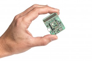
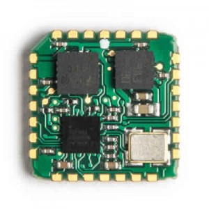
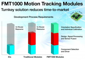
A motion tracker with advanced motion sensing technology is ubiquitous in applications from image stabilization in miniature cameras to control and navigation applications for UAVs. A MEMS-based IMU is the preferred motion sensing technology in industrial applications. The MEMS-based IMU’s increasing adoption rate and ever growing list of possible applications is a direct result of the technology’s versatility – high achievable target performance, highly reliable solid state technology in a very small form factor with very competitive pricing. The technology is also very attractive for high-volume consumer applications.

Sensor characterization and sourcing

Fig 2
Integration of inertial sensing starts with finding the right technology for the application. MEMS-based IMU motion sensors are available in chips at far less than $1 per axis, but the price range can exceed more than $100,000 per axis for optical inertial sensors. Next to the cost, there is also the aspect of suitability for an application. Even when considering MEMS-only inertial sensors, there is a huge variety of sensors. Some sensors have better performance under vibration, some have a good long-term stability and others may have low noise. The key is to find the sensor that best fulfills the need.
Simply understanding the sensor level specifications needed for a certain application can pose the biggest challenge. Often an application oriented development team can state (and get) requirements in terms or orientation accuracy needed or other high level functional specifications. Breaking these down to sensor level specifications is often much more difficult because of lack of time to dive into the specifics of the underlying technology.

Fig 3
There are several ways to find the best sensor, from comparing data sheets to doing a full characterization. As data sheets are not uniform and data is not always available for all conditions (e.g. vibrations, lateral acceleration), a full characterization targeted to your functional level specifications is often required. Next is the need for knowledge of MEMS, sensors and sensor fusion, which is also time-consuming.
Another challenge in the quickly changing landscape of MEMS sensors is that keeping track of changes and EOL/PCN-notices by vendors also consumes valuable time.
Dedicated MCU
Retrieving data from the MEMS sensors is the first step. The next step is to find an MCU to process this data. This requires making estimations to determine the required RAM and program memory, necessitating advanced knowledge of the sensor fusion algorithm, OS, drivers and signal processing. The type of processor selected has a significant impact on system architecture, and without experience in designing an IMU and associated signal processing and sensor fusion, this can be a long and complex process.
Signal Processing

OS drivers and communication
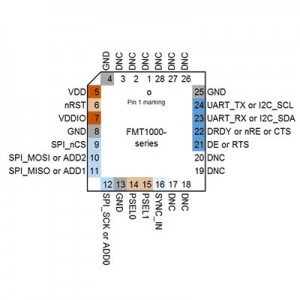
To communicate with the module, there needs to be drivers for the host, typically an application processor. Such drivers are specific for the module and include the communication protocol as well. Choices need to be made for the hardware layer (e.g. I2C, SPI, UART) and the communication protocol. The communication protocols used by some modules are flexible in terms of output configuration and/or integration level. For example, the communication protocol of Fairchild’s FMT1000 series is implemented for low-level binary communication, for C/C++ interfaces and as DLL/.so for Windows/Linux. Ready-to-run sample code is available for ARM® mbed™.
Test and Calibration
System integrators face several challenges when mounting MEMS on a board. For instance, the soldering process may influence the factory
(statistical) calibration. A module, in which the inertial sensors are mounted, doesn’t have these detrimental effects.
The calibration parameters in discrete inertial sensors are statistical values. This means that the variability is significant. Accelerometer biases of 30 mg (~2 deg roll/pitch error) are not an exception in low-cost MEMS sensors. Gyroscopes biases of up to 30 deg/s are also possible, although most gyroscopes biases are between -5 and 5 deg/s. A calibration improves the gyroscope bias repeatability up to +/- 0.5 deg/s, whereas accelerometer biases are limited to 2 mg (0.1 deg roll/pitch error). Mounting a module on another board does not influence the calibration parameters. As modules are simultaneously tested during calibration, production yield of the end-user application is significantly improved.
The capital investments for a calibration and test setup are significant, especially when the number of sensors per year is limited (under 10,000 units per year). In cases in which fewer than 10,000 units per year are required, the test and calibration costs already justify the higher price of a module.
Electronics and Mechanical Design
With magnetometers in many IMU designs, and with sensitive MEMS, the electronics design cannot be overlooked. Mechanical stress is often specified for the relatively large MEMS sensors components, so this should be taken into account. When something changes in the MEMS sensor component itself, the PCB of the end-user application may need to be redesigned. A turnkey module solves all these issues as it comes on a PCB that does not change interface and pinning and relieves the user from mechanical stress calculations.
Sensor Fusion Software
Sensor fusion software is required to interpret MEMS sensor data as useful orientation data, should the application demand this. Although sensor fusion algorithms are documented in literature, it is not as straightforward as just taking data and applying a filter. The sensor fusion algorithms of Fairchild’s FMT1000 series modules are optimized for several different use case scenarios based on the decades of application experience of Xsens, an industry leader in motion tracking acquired by Fairchild. The sensor fusion algorithm can be processed with different sets of settings, such as dynamic, human motion or high magnetic dependency. Performance testing on a wide range of test platforms ensures the best performance for many different applications. An added benefit of using Fairchild’s sensor fusion software is that the sensor fusion algorithm outputs different data in selectable output formats. Examples are free acceleration, where gravity is already subtracted; reference coordinate frames, for use in arbitrary alignment; and several fixed point and floating point output formats. Getting all this in a tested package will save you a lot of time and risk in the execution of your project.
The motion tracking module was designed keeping in mind user requirements and application needs. The design and development process took into thorough consideration the various aspects of producing and delivering a robust and high performance motion tracker module.
Authors:
Marcel Vanhak (Product Manager Motion Tracking),
Arun. Vydhyanathan (Lead Engineer Motion Tracking)


