Advancing communication and sensor technologies, driven by applications such as 5G, internet of things (IoT), and radar-enabled smart vehicles, are continuing to push component performance requirements as well as size and cost constraints. As a result, designers must develop more capable antennas and RF front-end components, adapting novel designs based on evolving techniques and materials, advanced device integration, and greater exploration of the design space based on unique topologies and architectures that might offer superior performance.
To this end, circuit, system, and electromagnetic (EM) simulation technologies must work seamlessly together along with design automation to help engineers define and manage complex RF electronics, including chip, package, and board structures. Simulation must accurately predict the response to standards-based signals, and the environment must help engineers create and organize simulation results to gain insight into component behavior. And these capabilities must integrate well with other design tools. These qualities are built into NI AWR Design Environment software, inclusive of Microwave Office, Analog Office, Visual System Simulator™ (VSS), AXIEM, and Analyst™ software, providing a robust and complete platform for RF/microwave engineers to develop these next-generation communication electronics.
The V14 release of NI AWR Design Environment software focuses on all stages of RF/microwave design with an emphasis on accelerating design starts through powerful network synthesis, enhanced design flow automation for printed circuit board (PCB) and module design, phased-array antenna system generation, and standards-compliant test benches.
Network Synthesis Wizard
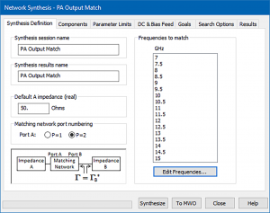
The new network synthesis wizard is an add-on utility for creating optimized two-port impedance-matching networks composed of discrete and distributed components. The user specifies the maximum number of sections and the types of components to include in the search space. Leveraging the evolutionary algorithms employed within AntSyn™ antenna design and synthesis software, the network synthesis wizard searches for the best circuit typologies and optimizes the component parameter values.
The network synthesis user interface lets designers interactively develop an unlimited number of networks optimized for noise, power, or matching networks between amplifier stages or between different components, such as an amplifier and an antenna. The optimum reflection coefficients are specified over frequency and can be provided in the form of load-pull data, network-parameter data files, or circuit schematics. On the synthesis definition tab, users can specify a default impedance or the impedance of the desired source/load network, as well as the desired match frequencies, as shown in Figure 1.
Figure 1: The network synthesis wizard guides designers through the development of inter-component and amplifier impedance matching.
PCB Import Wizard
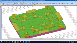
New functionality added to the PCB import wizard, an add-on utility, accelerates EM verification of designs created in board layout tools from leading CAD vendors such as Cadence, Zuken, and Mentor Graphics with powerful geometry selection and editing capabilities. RF design engineers can easily isolate areas of interest with powerful net and area selection for faster, more reliable EM analysis and optimization. Broadband S-parameters can be extracted for critical traces and densely-populated circuit boards, where unintended coupling and parasitics can be detected and addressed before they cause design failures. (Figure 2).
Figure 2: Enhanced PCB import wizard accelerates EM verification of designs created in board layout tools such as Cadence, Zuken, and Mentor Graphics with powerful geometry selection and editing capabilities.
The powerful new editing capabilities within the NI AWR Design Environment V14 release enable RF designers to easily set up complex imported PCB designs for analysis in the AXIEM or Analyst simulator. The new smart editing tool lets users interactively isolate board sections and multi-layer traces and vias, automatically define unlimited EM ports from the imported data, generate an EM structure with schematic view for surface mount component insertion, and related simulation set-up tasks.
Phased-Array Wizard
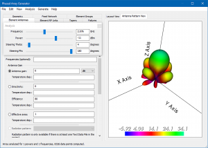
The newly-enhanced phased-array generator wizard lets users interactively design phased-array antenna systems and then generate detailed schematics diagrams suitable for further circuit, system and EM analysis. This add-on module allows users to easily define the array geometry (configuration), feed structures, gain tapers, and characteristics of individual elements and their respective RF links. (Figure 3).
Figure 3: The phased-array wizard supports array analysis and configuration optimization.
In the wizard, the array response is immediately displayed and reflects any changes due to the operating signal power level, beam steering, or element failures. Once the design is complete, the wizard generates a circuit or system diagram implementation that can be further analyzed in VSS/Microwave Office software or be incorporated into a larger, complete VSS communication system. The wizard also generates a layout of the entire array that may be used for full EM analysis with AXIEM or Analyst simulators or third-party EM tools such as ANSYS HFSS.
5G
Multiple-in-multiple-out (MIMO) and beam-steering phased-array antennas are enabling technologies for achieving the over-the-air spatial efficiency called for by 5G and emerging radar applications such as self-driving cars. In addition to the enhanced phased-array generator wizard, new standards-compliant WINNER II and 5G spatial channel models are available as an add on-module. This module provides highly-accurate modeling of channel-specific propagation effects that support more realistic link-budget analysis for rapid validation of end-to-end system performance and specification of individual component requirements.

Conclusion
The V14 release of the NI AWR Design Environment platform provides new and enhanced innovative solutions in design automation and simulation technology for the advancement of high-frequency electronic products serving the communication and aerospace/defense industries. As component requirements for these applications drive advances in semiconductor, PCB, and multi-chip module integration, NI AWR software addresses evolving product development challenges with powerful enhancements in design flow automation and greater speed and accuracy for its system, circuit, and EM simulation technologies. These new solutions enable device manufacturers and system integrators to meet challenging performance, size, and cost metrics, as well as time-to-market goals. Readers can learn more at ni.com/awr.


