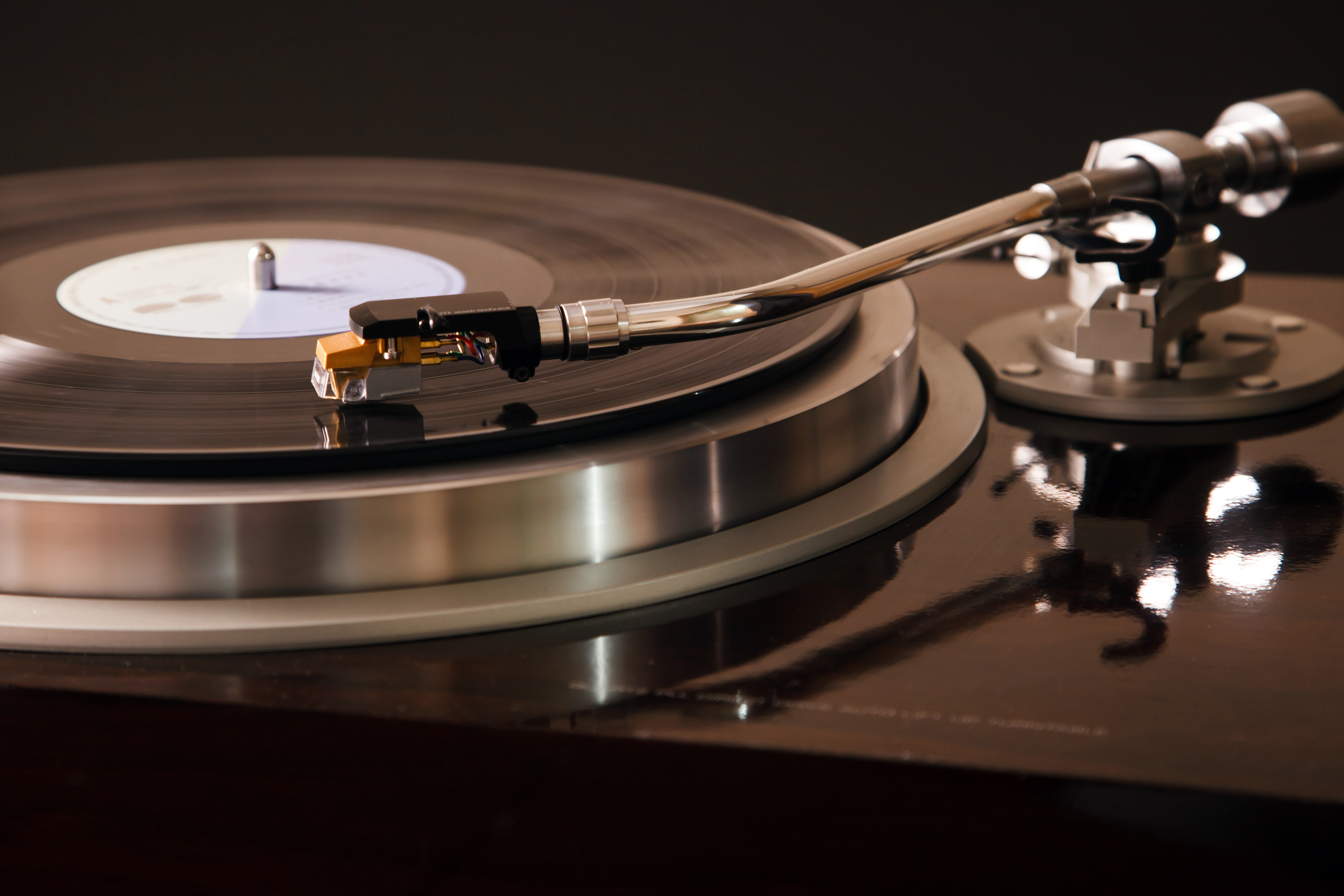
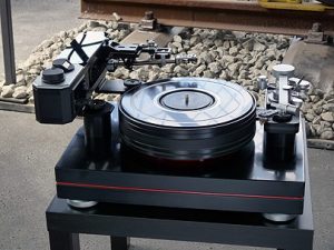
The Dereneville Modulaire MK III by AVDesignHaus is considered to be the best turntable in the world. Although the monetary investment for this fine system might be extremely high (in the higher six-figure range), audiophiles love it and will appreciate the excellent value it offers for the price. The complete deck comes with a polished Corian chassis, highly efficient shock absorbers for enhanced stability, and a heavy, magnetic, contactless bearing turntable to prevent even the possibility of friction.
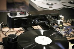
Although all of its mechanical parts are precision, handmade, unique pieces — making the turntable almost look like a scientific instrument used by the Department of Defense — what’s responsible for the “last mile” of sound quality are the smart microelectronics controlling the system’s electromechanical components. The major characteristic of the turntable [1] – stunningly pure, clear sound output – is made possible by the new fully automatic Dereneville DTT-01-S active linear tracking tonearm [2]. This tonearm is actuated by small stepper motors and electromechanically controlled by the latest generation of smart stepper motor driver chips from TRINAMIC Motion Control.
This white paper discusses the challenges the AVDesignHaus engineers were faced with while following their goal of designing the perfect turntable system, and how a smart piece of motion control silicon overcame this challenge by making it possible to totally silence the system’s electromechanical actuators.
|
|
A major question that will be answered is how stepper motors – which are typically not famous for smooth operation – became an enabler for the world’s most sophisticated turntable. What has changed so that simple stepper motors can be implemented in a top-of-the-line turntable?
The Engineering Challenge
Every analog audio enthusiast dreams of experiencing clear, high-fidelity sound with perfect trebles and no distortion while listening to their favorite tracks.
In an analog deck however, many factors distort the original track information. These include the lateral tracking angle error of the headshell and the stylus, mechanical vibrations within the whole system, or mechanical stress at the stylus and the record’s groove. In particular, higher audible frequencies and the record’s inner grooves are especially susceptible to these factors. The theory of record operation is based on the smallest micro-dynamic vibrations, so even the smallest deviations are absolutely performance-disturbing.
As lateral tracking angle errors increase, the total harmonic distortion of the sound output also increases. This results, among other things, in less precision and less ability for the listener to locate single voices or instruments.
From a technical point of view, the goal is to scan the original recorded vinyl track information with the stylus at a 90° angle to the groove and in optimal tangential alignment to the center of the record, exactly as the disc has been cut and pressed during the manufacturing process, without adding noise, without misreading information, and with minimal mechanical wear of the components.
Although there are nearly perfect, and similarly sophisticated, solutions for electronically amplifying the audio signal once it is read by the stylus of the tonearm, the engineer’s challenge is the physical and electromechanical task of making sure the stylus perfectly scans the vinyl’s groove information.
A conventional tonearm suffers from radial mounting and lacks active positioning. It passively follows the record’s track, which leads to skating forces and lateral forces. In contrast, an active linear tracking tonearm actively positions the stylus on the groove while always maintaining a tangential orientation to the center of the disc.
The Dereneville DTT-01-S tonearm has a linear drive based on hybrid stepper motors while the headshell itself is gimbal-mounted. The 90° angle of the stylus is permanently captured and maintained using precision laser optics and an advanced control algorithm. The control unit regulates the movement of the linear drive and the stepper motors. Stepper motors are ideally suited for this positioning task since they directly hold the commanded rotor position without requiring additional feedback and regulation.
A large portion of vibration and resonance inside the analog deck is dampened or completely removed by its heavy chassis, the use of air and magnetic suspension, and high-quality bearings. These items are aimed primarily at maintaining overall stability and protecting the unit from external forces.
However, the active linear tonearm’s electromechanical components, its small stepper motors, induce vibration directly at the tonearm’s fixture, which is passed on to the headshell and the stylus. This vibration adds noise, makes the headshell jolt, and reduces the quality of the audio signal.
But where do these additional vibrations come from when using stepper motors? What is their origin? Why of all motor types was a stepper motor chosen for the world’s best turntable tonearm?
A Brief Recap of Stepper Motors – Where Does the Noise Come From?
The linear tracking tonearm is both a very special and a typical application for stepper motors because a mechanical device needs to be positioned, and it needs to be positioned very precisely.
Generally, stepper motors are widely used in nearly all kinds of moving applications in automation, digital manufacturing, and medical and optical appliances.
The advantages of steppers are their comparatively low cost, high torque at standstill and at low speeds without using a gearbox, and inherent suitability for positioning tasks. In contrast to 3-phase brushless motors and servo drives, stepper motors do not necessarily require complex control algorithms or position feedback to be commutated.
The downside of steppers has been high noise levels, even at low speeds or at rest. There are two major sources of vibrations for a stepper motor: step resolution, and side effects that result from chopper and pulse width modulation (PWM) modes.
Step Resolution and Microstepping
|
|
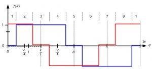
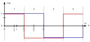
A typical stepper motor has 50 poles resulting in 200 full steps, each with a 1.8° full step angle, for a complete mechanical rotation of 360°. But there are also stepper motors with fewer steps, or even up to 800 full steps. Originally, these motors were used in full-step or half-step mode. The current vectors applied to the two motor coils A (blue) and B (red) show rectangle shapes when plotted over a fully electrical revolution (electrical 360°). The motor coils are either powered with full or no current in a 90° phase-shifted pattern as highlighted in Figures 3 and 4. One electrical revolution per period thereby consists of 4 full steps or 8 half steps. That is, a 50-pole stepper motor requires 50 electrical revolutions for one full mechanical revolution.
Low-resolution step modes like full or half stepping are the stepper motor’s primary source of noise. They introduce tremendous vibrations that spread throughout the whole mechanics of a system, especially at low speeds and near certain resonance frequencies. At higher speeds, due to the moment of inertia, these effects decrease.
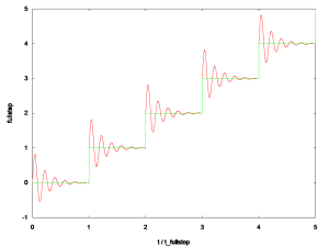
The rotor can be imagined as a harmonic oscillator or spring pendulum as depicted in Figure 5. After a new current vector is applied by the driver electronics, the rotor steps to the next full- or half-step position in the direction of the new position commanded. Similarly to a pulse response, the rotor overshoots and oscillates around the next position, leading to mechanical vibrations and noise. The movement is far from being smooth, especially at lower speeds. The physical background on this is detailed in [3].
Figure 5 – Pendulum behavior of the rotor leads to vibrations
To reduce these oscillations, a mechanism called microstepping can be applied. This divides one full step into smaller pieces, or microsteps. Typical resolutions are 2 (half-stepping), 4 (quarter-stepping), 8, 32, or even more microsteps. The stator coils are not powered with either full or zero current but with intermediate current levels approximating a complete sine wave shape over 4 full steps. This positions the permanent magnet rotor in intermediate positions in between two subsequent full steps. This even allows for special custom current waveforms adapted to the stepper motor’s physics or application.
The maximum resolution for microstepping is defined by the driver electronics’ A/D and D/A capabilities. Trinamic’s stepper motor controller and drivers allow the use of a stepper motor with up to 256 (8-bit) microsteps per full step, using the chips’ integrated configurable sine wave tables or even full custom current waveforms.
The outcome of using this high microstep resolution is that the motor’s rotor is now stepped in much smaller angles, or smaller distances. When switching to a new position, the over- and under-shoots as shown in Figure 5 are drastically reduced. Figure 6 shows this difference.
Figure 6 – Reduction of motor vibrations when switching from full-step to high microstep resolutions
Chopper and PWM Modes
Another source of noise and vibration originates from the conventional chopper and PWM modes typically used with stepper motors. The parasitic effects of these modes are often neglected due to the dominant impact of coarse step resolution. But with improvements in step resolution using microstepping, these parasitic effects become apparent and even audible.
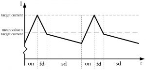
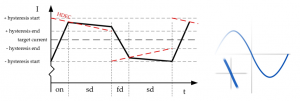
The classic constant off-time PWM chopper mode is a current-controlled PWM chopper that works with a fixed relationship between fast decay and slow decay phases. At its maximum point, the current reaches the specified target current, which results in an average current that is lower than the desired target current, as shown in Figure 7.
Figure 7 – Constant off-time (TOFF) PWM chopper mode: average current is not equal to target current
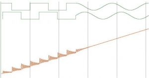
In a full electrical revolution this results in a plateau around the zero-crossing area of the sine wave when the sign (direction) of the current changes. The impact of this plateau is a small period with zero current in the motor windings, meaning there is no torque at all. This leads to wobbling and vibrations, especially at lower speeds.
Figure 8 – Zero-crossing plateau with classic off-time chopper modes
In contrast to a constant off-time chopper, Trinamic’s SpreadCycle™ PWM chopper mode applies a hysteresis function that automatically uses a fitting relation between slow and fast decay periods. The average current reflects the configured nominal current. There is no plateau in the zero-crossing region of the sine wave. This reduces current and torque ripple and a true sine wave form is approached, resulting in a much smoother motor operation compared to a constant off-time PWM chopper. This is especially important at standstill and slow to moderate speeds.
Figure 9 – SpreadCycle hysteresis chopper with clean zero crossing
How To Totally Silence Stepper Motors
Although microstepping reduces a large part of the vibration caused by low step resolutions, high microstep resolutions make it easier to perceive other sources of vibration. Advanced current-controlled PWM chopper modes like Trinamic’s SpreadCycle™ algorithm, which is implemented in hardware, reduce vibration and wobbling to a large extent. This is sufficient for many standard applications and also ideally suited for higher-speed applications.
But even with current-controlled chopper modes like SpreadCycle there is still a little bit of audible noise and vibration due to unsynchronized motor coils, regulation noise of a few millivolts at the sense resistors, and PWM jitter. This noise and vibration can be critical for high-end applications, slow- to moderate-speed applications, and any applications where noise is unacceptable. It was intolerable for the Dereneville DTT-01-S linear tracking tonearm, because the noise coming from the microstepping drive and hybrid stepper is superimposed on the audio signal, especially within the plain grooves at the transition between individual tracks.
Trinamic’s StealthChop™ algorithm [4], also implemented in hardware, ultimately silences stepper motors. But what is StealthChop actually doing to a stepper motor, and why doesn’t it generate additional noise and vibrations? StealthChop follows a different approach compared to current-based chopper modes like SpreadCycle: it is a voltage chopper-based technology that’s responsible for the noiseless and smooth movement of the Dereneville DTT-01-S tone arm and stylus. Combined with closed-loop tracking angle regulation and precision laser optics, this results in a maximum tracking angle error of headshell plus stylus of <0.05°. A good conventional pivoted tonearm has a typical tracking angle error of <2°-3°, and also suffers from skating forces and mechanical wear of the groove.
The TMC5130A-TA – a small, smart stepper motor driver and controller IC that includes StealthChop mode – was the ultimate solution for this remarkable analog record player. In addition to StealthChop, Trinamic has improved voltage mode operation and combined it with current control. To minimize current fluctuation, the TMC5130A-TA chip’s driver regulates voltage modulation based on the current feedback. This allows the system to self-adjust to the motor’s parameters and the operating voltage.
|
|
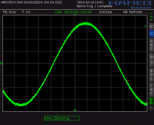
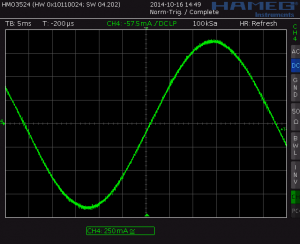
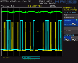
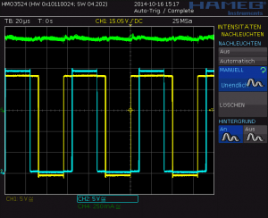
Small oscillations caused by the regulation algorithms of direct current control loops are eliminated. As SpreadCycle and other current-regulated chopper principles always react to the coil current measurement on a cycle-by-cycle basis, a few millivolts of noise – which are always present in complex systems – as well as electric and magnetic coupling between both coils within the motor, lead to small variations of the resulting motor currents and thus influence the chopper. Figures 10 and 11 compare voltage-controlled StealthChop with current-controlled SpreadCycle. The zero-crossing behavior of StealthChop is perfect: when the signs of the current value change from plus to minus or vice versa, there is no plateau, but a straight crossing of the zero-current level, since the current is modulated based on the PWM duty cycle. At 50% PWM duty cycle, the current is actually zero.
StealthChop adjusts the duty cycle of the PWM to control the motor current. The PWM frequency is constant. In contrast, current-controlled chopper schemes adjust the frequency to control the motor current. Here, the current ripple is higher. Furthermore, the current ripple leads to an eddy current in the stator magnet material, which leads to power losses, which makes StealthChop even a bit more efficient although this is hard to measure.
|
|
These variations of the PWM frequency (frequency jitter due do the current control loop) are in an audible range. They can lead to hissing and chirping sounds and other high-pitched noise caused by magnetostriction of the stator material and a subsequent mechanical vibration of the motor axis. Here, StealthChop’s fixed chopper frequency works well. There are no variations of the chopper frequency other than those variations commanded by the microstep wave sequencer when the motor is to be moved.
Motor drivers equipped with StealthChop combine current waveforms that closely replicate analog — which somehow perfectly fits the application of the Dereneville analog deck — with some minor improvements in power consumption at no additional cost. The result is whisper-quiet motion. Except for the ball bearing noise, which cannot be changed, StealthChop delivers exceptionally quiet stepper motor performance. Applications using StealthChop have achieved noise levels of 10dB and more below classical current control. As we know from physics, a change of -3dB represents a decrease of approximately half the noise or sound level.
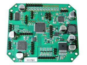
Figure 14 shows the final controller PCB for the electromechanical actuators of the tonearm along with Trinamic’s smart stepper motor driver solutions. It is assembled and manufactured by Dischereit [5].
Figure 14 – The controller PCB for the electromechanical actuators of the tangential tonearm DTT-01-S, along with Trinamic’s smart stepper motor driver solutions. (Courtesy of AVDesignHaus)
What Has Changed For Stepper Motors?
Stepper motors today are the same cost-effective actuators that they have been for many years. They are still manufactured and assembled by the same machines using the same processes and materials. Even their general mode of operation is the same.
But compared to the old days when they were driven using simpler controller units, the real potential of these motors can now be unleashed with much more advanced algorithms and highly integrated microelectronics. More intelligence directly at or in the motor driver electronics closes the local loops gathering and measuring information in situ at or near the actuator, which is the only place where they’re available, and processes this information in real-time directly within the driver. StealthChop is a perfect example of this, as its algorithm is closely related to the PWM chopper.
In addition, information can be fed back to the higher, application-level controller. Classical stepper driver solutions primarily work in only one direction, toward the motor. All of Trinamic’s smart stepper motor driver solutions allow bi-directional communication via fast, state-of-the-art interfaces. These interfaces also enable monitoring of different kinds of status and diagnostic information, which can in turn be used on the application level to increase performance, efficiency, or reliability, for example.
This new generation of motion and motor control solutions also offload the higher, application-level controller from compute-intense, real-time, or repetitive tasks that do not necessarily belong to the actual application level but are required to drive and control the motor; reduce application development time and effort; and even reduce the overall PCB area and bill of materials (BOM). A huge portion of real-time motion control functions is available in these smart microelectronic devices. such as motion profile calculation, encoder interfacing, and end-switch detection.
All of this raises the abstraction level and makes motor and motion control a ready-to-use building block with supreme quality – and yet still uses the very same “old” stepper motors.
Summary & Conclusion
The new fully automatic tangential tonearm Dereneville DTT-01-S as used in the remarkable Dereneville Modulaire MK III analog turntable redefines the standard in the analog HiFi world. It is truly the first of its kind.
For ultra-quiet operation, the tonearm relies on the TMC5130A-TA stepper motor driver and controller. This smart IC with its StealthChop mode for ultra-silent stepper motor operation (no audible noise and no physical vibrations) adds the necessary final touch to this perfect piece of engineering: it is responsible for the pure sound output audiophiles love to hear, as loud as possible.
Although manufacturing volumes of this exclusive analog deck might be relatively low when considering the IC business, there are many comparable applications that can take advantage of this smart IC technology. These include wafer handling in semiconductor manufacturing equipment, medical applications, and lab automation. All share similar quality requirements for low noise and vibration. Additionally, there are other applications with – up to now – lower requirements for noise, vibration, and motion quality that can be improved considerably with this technology. There are also more and more emerging embedded applications that actually only become possible – from a qualitative and quantitative point of view – with such smart solutions. These include, for example, 3D printing and desktop manufacturing applications [6] [7], advanced personal medical devices where audible noise is unacceptable, camera sleds, and advanced CCTV and surveillance cameras. The TMC5130A family of ultimate stepper motor drivers and controllers reflect a megatrend in motion control
About TRINAMIC Motion Control
Instead of semiconductor makers that just want to sell more chips, TRINAMIC Motion Control (TMC) began with engineers who wanted to design better drives. Its founders knew that designing motion control technology in hardware, not software, was essential for motors that work efficiently, reliably, smoothly, and quietly.
The Hamburg, Germany-based fabless semiconductor company’s own motion control architecture divides power electronics into three building blocks: a microcontroller for digital processing, a driver that translates digital signals into electrical power, and a gate driver plus power switches. This simplifies development, and makes it easier to design components best suited for each block. In 2015, TMC became the first supplier worldwide with an EtherCAT-compliant slave-controller IC for integrating complex, real-time, latency-free I/O peripherals.
TMC now has over 20 years of application experience in embedded motion control. It develops and sells ICs, modules, and integrated mechatronics to market-leading manufacturers worldwide. Examples include Ecovent, GE, Honeywell, Kuka, Markforged, Össur, Xerox, and Zeiss. The company’s products have been integrated into a wide range of applications in digital manufacturing, biotechnology, lab automation, materials handling, and factory automation.
References:
[1] AVDesignHaus Dereneville Modulaire https://www.avdesignhaus.de/AnalogLaufwerkbau-Node_15750.html
[2] AVDesignHaus Dereneville DTT-01-S https://files.avdesignhaus.de/Dateien/PDF_HT_Horstmann.pdf
[3] Larsson, L., “Micro Step vs. Full Step – A Quantitative Competition,” SAE Technical Paper 2003-01-0093, 2003, doi:10.4271/2003-01-0093. [4] Trinamic’s StealthChop Technology https://www.trinamic.com/technology/adv-technologies/stealthchop/
[5] D-E-K Dischereit elektronische Komponenten GmbH & Co. KG https://www.dischereit.de/
[6] Trinamic TRAMS Board for 3-D Printer Noise Reduction – Another Geek Moment | DigiKey Electronics https://www.youtube.com/watch?v=csAMwhsvuwc
[7] Trinamic – StealthChop Silent 3D Printer Demo https://www.youtube.com/watch?v=qRrJK5jTZSA


