The changes occurring in the medical and fitness fields, along with their associated electronic devices, can be called truly revolutionary. The demands of today’s healthcare-device markets are many, varied and challenging. Devices that were once primarily found in hospitals are now used for home-medical applications, as well as fitness monitoring.
For example, the capability to measure heart rate and blood oxygen levels is showing up more often now in consumer products. These measurements can be taken using pulse oximeters that are now available as both home-medical devices as well as part of integrated wrist-worn fitness activity trackers.
This article will cover the basics of pulse oximetry for medical and fitness applications. It will also examine a pulse-oximeter design example that demonstrates the measurement of heart rate and blood oxygen levels.
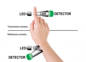
Figure 1: Two Oximetry methods
What is Oximetry?
Oximetry is the measurement of oxygen saturation in blood, and is usually expressed as a percentage. A pulse oximeter is a non-invasive device that measures the oxygen saturation of a person’s blood, as well as their heart rate. Pulse oximeters are easily recognized by their associated clip-type probe, which is generally applied to a patient’s finger.
A pulse oximeter can be a stand-alone device, part of a patient-monitoring system, or integrated into a wearable fitness tracker. Accordingly, pulse oximeters are used by nurses in hospitals, outpatients at home, fitness enthusiasts at the gym and even by pilots in unpressurized aircraft.
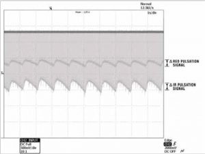
Figure 2: Real-time Red and Infrared (IR) pulsation signals, as captured by an oscilloscope
What is Blood Oxygen Saturation?
Blood oxygen saturation is measured by examining hemoglobin, which is the oxygen-carrying pigment of red blood cells that gives them their red color and serves to convey oxygen to the tissues. Hemoglobin is found in two forms. The first is called oxidized hemoglobin, which is denoted as HbO2 (i.e., oxygen-loaded). The second is called reduced-oxygen hemoglobin, which is denoted as Hb (i.e., oxygen-depleted)
So, blood oxygen saturation (SpO2) is the ratio of Oxy-hemoglobin to Deoxy-hemoglobin. This can also be expressed as:
SpO2=HbO2/ (Hb + HbO2)
The value of blood oxygen saturation is expressed as a percentage. A normal reading is typically 97% or higher.
How Does a Pulse Oximeter Measure Blood Oxygen Saturation (SpO2)?
One of the really interesting things about hemoglobin is how it reflects and absorbs light. For example, Hb absorbs more (and reflects less) visible red light. HbO2 absorbs more (and reflects less) infrared light. Since blood oxygen saturation can be determined by comparing the values of Hb and HbO2, one method for doing this is shining both a red LED and an infrared LED through a body part (such as a finger or wrist), and then comparing their relative intensities. There are two common methods of doing this: (1) measuring the light transmitted through tissue is called transmissive oximetry, and (2) measuring the light reflected by tissue is called reflectance oximetry (See Figure 1).
Generally, most hospital patient-monitoring systems have an integrated transmissive pulse oximeter. On the other hand, many of the newer, high-end wearable fitness devices utilize the reflectance-pulse-oximetry method.
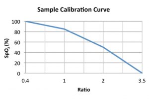
Figure 3: Example calibration curve
How Does a Pulse Oximeter Measure Pulse Rate?
When your heart beats, it pumps blood through your body. During each heart beat, the blood gets squeezed into capillaries, whose volume increases very slightly. Between heart beats, the volume decreases. This change in volume affects the amount of light, such as the amount of red or infrared light, that will transmit through the tissue. Though this fluctuation is very small, it can be measured by a pulse oximeter using the same type of setup that is employed to measure blood oxygen saturation.
Detailed Theory of Operation
Typical pulse oximeters monitor the oxygen saturation (SpO2) of a human’s blood, based on the red light (using a 600-750 nm wavelength) and infrared light (using a 850-1000 nm wavelength) absorption characteristics of oxygenated hemoglobin (HbO2) and deoxygenated hemoglobin (Hb). This type of pulse oximeter flashes the red and infrared lights alternately through a body part, such as a finger, to a photodiode sensor.
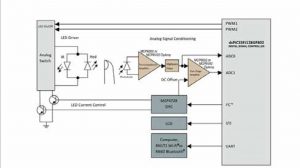
Figure 4: Transmissive pulse oximeter system block diagram
The photodiode is normally utilized to receive the non-absorbed light from each LED. This signal is then inverted using an inverting operational amplifier, or op amp. The resulting signal represents the light that has been absorbed by the finger, as shown in Figure 2.
The pulse amplitudes (Vpp) of the red and infrared signals are measured and converted to Vrms, in order to produce a ratio value, as given by the equation below…
Ratio=
(Red_AC_Vrms/Red_DC) /
(IR_AC_Vrms/IR_DC)
The SpO2 can be determined using the ratio value and a look-up table that is made up of empirical formulas. The pulse rate can be calculated based on the pulse oximeter’s Analog-to-Digital Converter (ADC) sample number and sampling rate.
A look-up table is an important part of a pulse oximeter. Look-up tables are specific to a particular oximeter design and are usually based on calibration curves derived from, among other things, a high number of measurements from subjects with various SpO2 levels. Figure 3 shows an example of a calibration curve.
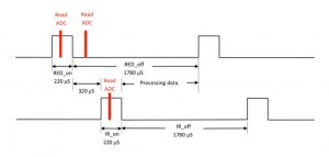
Figure 5: Timing diagram
Circuit Design Description
The following example will detail the different sections of a transmissive pulse-oximeter design. This design, as shown in Figure 4, demonstrates the measurement of both the pulse rate and blood oxygen saturation levels.
Probe
The SpO2 probe used in this example is an off-the-shelf finger clip that integrates one red LED and one IR LED, plus a photodiode. The LEDs are controlled by the LED driver circuit.
The red light and IR light passing through the finger are detected by the signal-conditioning circuit, and are then fed into the 12-bit ADC module that is integrated into the Digital Signal Controller (DSC), where the percentage of SpO2 is calculated.
LED Driver Circuit
A dual single-pole, double-throw analog switch, driven by two PWM signals from the DSC, alternately turns the red and infrared LEDs on and off. In order to acquire the proper number of ADC samples and still have enough time to process the data before the next LED turns on, the LEDs are switched on and off according to the timing diagram in Figure 5.
The LED current/intensity is controlled by a 12-bit Digital-to-Analog Converter (DAC), which is driven by the DSC.
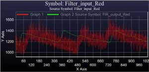
Figure 6: Input and filtered data
Graph 1, shown in red, is the input signal to the FIR filter
Graph 2, shown in green, is the output signal from the FIR filter
X-Axis shows the number of ADC samples
Y-Axis shows the ADC code values
Analog Signal-Conditioning Circuit
There are two stages in the signal-conditioning circuit. The first stage is the transimpedance amplifier, and the second stage is the gain amplifier. A high-pass filter is placed between the two stages.
The transimpedance amplifier converts the few micro amps of current, which are generated by the photodiode, to a few millivolts. The signal received from this first-stage amplifier then passes through a high-pass filter, which is designed to reduce background-light interference.
The output of the high-pass filter is then sent to a second-stage amplifier with a gain of 22 and a DC offset voltage of 220 mV. The values for the amplifier’s gain and DC offset are set to properly place the output signal level of the gain amplifier into the MCU’s ADC range.
Digital Filter Design
The output of the analog signal-conditioning circuit is connected to the DSC’s integrated 12-bit ADC module. For this example, we utilized a dsPIC® DSC from Microchip Technology. The dsPIC33FJ128GP802 used in this design enabled us to take advantage of not only its integrated DSP capabilities, but also of Microchip’s Digital Filter Design Tool.
One ADC sample is taken during each LED’s on-time period, and one ADC sample is taken during both LEDs’ off-time periods. Due to the challenges of taking light-based measurements through organic tissue, the filter design tool was used to implement a 513th-order, digital-FIR, bandpass filter, which enabled us to filter the ADC data. This filtered data was then used to calculate the pulse amplitude, as shown in Figure 6.
The specifications of our FIR bandpass filter are:
Conclusion
The home-medical and fitness markets are growing at a rapid pace. The demand for devices that can measure heart rate and blood oxygen levels will only increase over the next few years. Pulse-oximeter reference designs, such as the one described in this article, can be very helpful in providing medical and fitness device designers with a head start toward getting their designs into production and out to market.
Note: dsPIC is a registered trademark of Microchip Technology Incorporated in the U.S.A. and other countries. All other trademarks mentioned herein are the property of their respective companies.
Resources
Pulse-Oximeter Design
• Principles of Pulse Oximetry Technology (2002). Oximetry.org. Retrieved April 23, 2014: https://www.oximetry.org/pulseox/principles.htm
• Microchip Technology Inc., Online Medical Design Center: https://www.microchip.com/pagehandler/en-us/products/medical/pulseoximeter.html/
• Or go to and find Pulse Oximeter under the left Applications navigation bar:https://www.microchip.com/medical
• Webster, J. G. (1997). Design of Pulse Oximeters. Bristol and Philadelphia: Institute of Physics Publishing.
Pulse-Oximeter Simulation
• Fluke Biomedical. (2007). Index 2XL SpO2 Simulator User Manual.


