Many articles on interconnects discuss bleeding edge new technologies, new products, or provide guidelines on optimizing system performance. Having said that, standard pitch (2.54, 2.00, or 1.27 mm centerline) board-to-board interconnects are still huge sellers and ubiquitous in the electronics industry.
These two-piece connectors are not as sexy as using ultra-high-density interconnects with PAM4 to achieve 56 Gbps serial channels, but they look mighty appealing if your job is to identify and design-in reliable board-to-board interconnect systems.

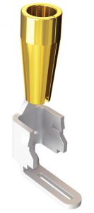
FIGURE 1: Multi-finger, heat-treated BeCu contact for high cycle applications
There are several design factors that determine the success of the interconnect system. Two of the most important considerations are selecting the right contact, and selecting the right plating for that contact.
Selecting the right contact helps ensure your interconnect system will meet the standards it is supposed to meet – whether it is a high-cycle application, or high shock and vibration, or an interconnect that is going to see very little stress in its life.
The following is a basic overview of contact design considerations:
CONTACT BASE METAL:
Three commonly used contact base metals include phosphor bronze (PhBr), beryllium copper (BeCu), and brass. Brass has a tensile strength of 69 MPa – 434 MPa (Mega Pascal, unit of pressure and tensile strength). Compare this to Phosphor Bronze with 131 MPa – 552 MPa, and BeCu with 965 MPa – 1205 MPa.
Obviously, in industrial, high-risk, hostile-environment applications, a greater yield/tensile strength would be desired, and in other applications a more cost effective option would be appropriate. Brass is generally only recommended for simple, low-cycle applications. While not as conductive as brass, phosphor bronze boasts a higher tensile strength. For the best of both worlds, beryllium copper not only offers the highest strength of the three, but its conduction is close to that of copper, making it well-suited for strong, reliable connections.

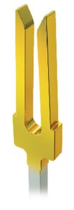
FIGURE 2: Phosphor bronze contact designed for rugged applications
CONTACT DESIGN BY END-APPLICATION:
High reliability, high cycle contacts are usually made of beryllium copper. BeCu provides a strong combination of mechanical and electrical properties for high reliability interconnections. High reliability contact systems frequently have multiple points of contact, usually three to four “fingers.” (FIGURE 1: Multi-finger, heat-treated BeCu contact for high cycle applications)
At the other end of the spectrum, some interconnect systems have a relatively stress-free life with few cycles, possibly in an office environment. A single beam contact system is usually sufficient for these types of applications, and if it is made of phosphor bronze or beryllium copper, it will usually withstand up to 100 cycles.
A third contact option is one designed for high-retention, or “rugged” applications. The geometry of the contact beams increase the normal force and withdrawal force of the mating terminal. Long beams and therefore extended insertion depth make it rugged. (FIGURE 2: Phosphor bronze contact designed for rugged applications.)
While the focus of this article is contact design, we would be remiss if we did not mention insulator design in any discussion of rugged interconnect applications. Plastic insulator design features that are useful in environments requiring rugged connectors include:
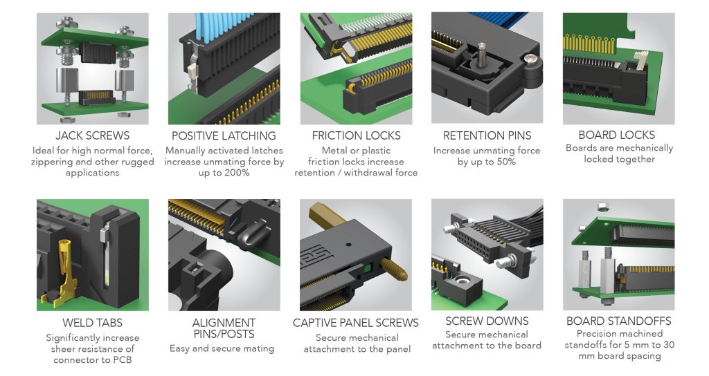
• Board locks on connectors that mechanically lock two together two printed circuit boards.
• Positive latching systems on discrete wire and IDC cable systems. Manually activated latches can increase unmating force by up to 200%.
• Screw downs which secure the connector mechanically to the board.
• Weld tabs, which significantly increase shear resistance of the connector to the PCB
(FIGURE 3: Rugged features on insulators which increase the ruggedness of the connector)

FIGURE 3: Rugged features on insulators which increase the ruggedness of the connector
PLATING: Plating is another critical design factor that determines the success of the interconnect system. The best plating finish is whatever material meets your requirements at the lowest cost.
Gold is generally specified for high reliability or low voltage and current applications. Even in very hostile environments, it will remain free of oxides which could cause an increase in contact resistance. Gold is also used for contacts that will see a large number of cycles because excellent electrical connection can be made with minimum contact pressure.
Gold is a significant cost adder to most interconnect systems. Of course gold is susceptible to price fluctuations. The impact of the price of gold on a connector has been alleviated with the adaptation of using less gold in non-critical applications. Originally, Bellcore specifications required 50 µ inches of gold plating over nickel, for applications including leads, cables, and grounding points.
In a bid to remain competitive but still employ the advantages of gold, many companies lowered their minimum gold plating thicknesses to 30 µ or 10 µ inches, or even flash gold.
Tin is a low-cost alternative to gold plating. It has good conductivity and solderability, but forms an oxide coating which must be penetrated for electrical connection. It is also susceptible to a form of corrosion known as fretting. Tin is used in connector systems where fewer cycles are expected, or where the contact can be designed to apply high normal forces which will cause sufficient sliding (i.e., wiping action) during lead insertion, to break the tin oxide surface film.
The wear caused by this wiping action is one factor that limits tin plated contacts to fewer cycles than gold. It also requires an increased plating thickness, often 150 µ inches.
While economics are an important consideration, the requirements of a particular product are more likely to dictate which plating is used. Selective gold/tin plating is a popular plating option because it provides designers with the best of both worlds. The critical contact area has the reliability of gold, and the tail has the lower cost and solderability of tin.


