A terminal block is one method of connecting a selection of different electrical wires. They come in a variety of shapes and sizes so you can normally find one that will be compatible with whatever project you are carrying out. However, the difference between blocks can lead to problems if an incorrect type is used or if it is not connected properly.
Terminal blocks are widely used in some major industries where wiring between equipment’s widely used. Major application and industries widely adopted TBs are Industrial Controls, HVAC equipment and controls, building automation, Communications equipment, Test and Measurement, Fire & Security, Lightning.
Use of TBs for connection simplifies wire termination and removal from contacts. Allows easy and cost-effective servicing of PCB or Wire-termination corrections Prevents over-insertion of wire, compact design allows for flexibility to meet unique design requirements
Offering a wide variety of industry standard options provides manufacturing and installation personnel new freedom in product design while maintaining intuitive operation and a lower installed cost. Selection of models for PCB mounting, DIN Rail support, color selection, different connection method (screw, fast connection) , labeling option , support of popular wire gages based on application help user to find the proper solution.
Typical terminal Block connectors feature various wire termination methods including rising cage clamp, wire protector, spring, IDC and crimp snap. The design of Terminal Block connectors consists of one-piece board mount terminal blocks and two-piece plug connectors with mating straight and right-angle shrouded headers. A special version – which can be mated either 90° or 180° – completes the product line. Board mount connectors, as well as pc board plugs and headers, are stackable end-to-end without loss of centerline spacing.

15EDGKNH/15EDGKNHM/15EDGKNHG-3.5
New Terminal Block Implementation LED Light
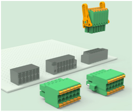
Several vendors introduce lately solutions for the booming LED lightening industry. New PCB connector adapters SMT usually, enable the quick, easy, and secure connection of flexible LED PCBs when combined with series of connectors. The PCB adapters can be used as an extension, as a corner connection, or as a T-distributor. The white PCB adapters are designed for 2- and 4-position applications with 8- or 10-mm-wide LED strips. UL-approved materials ensure that they can be safely used in applications requiring UL approval. Features and benefits of the newly solution supporting LED strips are :Tool-free termination saves time and cost while reducing errors, High-current capacity enables long LED strips to be connected without an additional power supply, Locking pin ensures secure connection to the PCB, Rated up to 5 A and 60 V UL.
The new connectors support reliable long-term installation of LED modules (assembled from LED arrays mounted on rigid and thermally conductive substrates for optimal heat dissipation) into a wide variety of applications, e.g. high/low bay indoor lighting, street lighting, floodlighting and emergency lighting.
Applying SMT TBs with surface-mount reflow soldering processes greatly simplifies LED module PCB assembly. Connecting the conductors in lighting fixtures was formerly often done using hand soldering. This is often unreliable and prone to error when using printed circuit boards with a metal core, due to the high degree of heat dissipation. The optimized design of the new connector hold-downs ensures rugged solder-pad retention and supports reliable handling during equipment final integration.
PCB mounting design options commonly include a horizontal male and a discrete wire push-in spring-cage terminal block part. Both are made from high-temperature LCP plastic which is completely colour-stable after the SMT assembly process and UV resistant for long-term installation. As a result they minimise shadowing effects within the light fixture. Pluggable female, discrete wire, push-in spring-cage cable connectors are also available. These have a strong but flexible locking-latch design which is highly damage resistant and ensures dependable mating.
Implementing TBs method under explosive environment
Implementing TBs under Explosion proof environment required taking into consideration several new aspects and addresses it under well-known standard such as ATEX. The risk of explosion is particularly high in certain types of industries, which generate inflammable gas, inflammable liquid or inflammable dust. Indeed, the new ATEX directive now considers the explosion risk caused by dust. Refineries, Petrochemical and chemical industries. An explosion can occur if the following factors arecombined: Presence of inflammable substances Presence of an ignition source or inflammation source: fire, flame, electrical or mechanical sparks, overheated surfaces, electrostatic Discharges Oxygen.
In order to be used under explosion proof environment item should be design and certified to meet
ATEC and or IECEX standard. Industry support variety of products that are certified for the appropriate standard already.

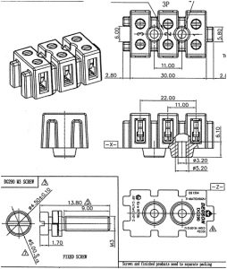
IECEX , ATEX Certified Terminal Block DG 290
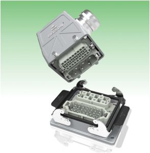
Heavy Duty connectors
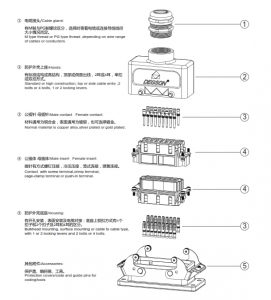
To address challenging environments demanding applications and markets such as industrial Automation, Transportation, Robot, manufacturers lately introduced solution which provides flexibility to build “your own solution”. Introducing variety of bodies support flexible number of pins, different housing shapes, implementing locking mechanism and use of different pins customer can build his own solution to fit his environment, product.
Heavy-duty connectors are used wherever there is a need for a secure, simple and time-saving assembly of machinery and facilities. The connector housings are made of die-cast aluminum and offer excellent protection against dirt, moisture and mechanical stress. Special modular connectors make it possible to integrate signals, power supply, pneumatics, and data connections into a single connector.
The connectors housing, sealing and locking mechanism protect the connection from external influences such as mechanical shocks, foreign bodies, humidity, dust, water or other fluids such as cleansing and cooling agents , oils, etc. The degree of protection the housing
Inserts
A heavy-duty connector consists of a connector insert and its protective enclosure. The insert is therefore the heart of the heavy-duty connector. It is responsible for electrical functioning. Connector inserts are commonly made from high-quality insulation materials, which allow secure transmission of high voltages in a tight space. Moreover, it use only a single type of plastic This plastic is UL listed, and suitable for different applications

Heavy Duty Connector Finished product
Modular Inserts
Modular inserts are the solution for many applications. It is consisting of modules and frames. Together they form a complete insert that integrates without difficulty into an HDC housing. The system allows you to choose combinations of different modules yourself and insert them in a frame.
Housings
A heavy-duty connector consists of a connector insert and its protective enclosure. Commonly enclosures are made of high-quality die-cast aluminum. Thus they are impact- and corrosion-resistant, yet still compact and lightweight. Their stainless steel clips make them totally water- and dust-proof. They can be used under the harshest environmental conditions and are resistant to frost and vibrations. With use proper gland the connector can meet IPXX resistance against water and dust.
Lily Hu


